

 Arabic
 Spain
Spain Germany
 France
 Japan
Japan Portuguese
 Russian
 Chinese
 Thailand
 Vietnam
 Indonesia
 India
IndiaNews
THE PIONEER IN FACADE SOLUTIONS


A water stain on the interior side of a curtain wall seems to give the investigation a clear starting point. But it often does not. Understanding how water moves through drainage cavities, joints, transitions and facade layers is essential to finding the real entry point.
A water stain on the interior side of a curtain wall seems to give the investigation a clear starting point.But it often does not.
The visible leak may appear around a window head, several meters below a panel joint, or beside an interior mullion. The first instinct is usually to inspect the sealant directly above the stain. Sometimes that works. Often, it does not.
The reason is simple: water does not always enter where it eventually appears.
Once rain passes through an exterior joint or a vulnerable transition, gravity, wind pressure and the internal geometry of the facade can move it along a completely different route.
This makes curtain wall leakage less like finding a hole and more like tracing a drainage network.
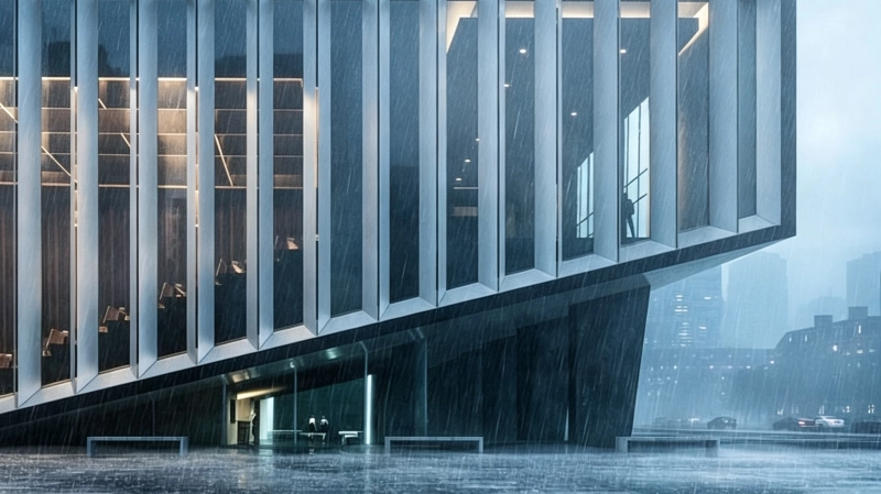
Water may appear at one location while entering the facade somewhere else. Understanding this migration is the first step toward a more reliable leakage investigation.
Consider a facade exposed to wind-driven rain.
Water enters through a small discontinuity at a horizontal joint. Instead of immediately reaching the interior, it enters the cavity behind the external cladding.
From there, it may travel sideways along a horizontal member, move downward through a vertical cavity, collect at a transition, and finally emerge through an opening around an interior frame.
The building occupant sees the final point.
The water entered somewhere else.
Once water enters the outer layer, gravity, wind pressure and internal facade geometry can move it through cavities, horizontal members, vertical routes and transitions before it finally becomes visible.
This explains why repeated sealant replacement sometimes fails to solve recurring leakage. The repair may address the visible symptom without correcting the drainage path that allowed water to travel through the facade.
For large curtain walls, this distinction is critical. A facade contains thousands of interfaces, connections and transitions. The more complex the system becomes, the more difficult it is to identify the original entry point simply by looking at the interior water stain.
A reliable curtain wall should not rely on the assumption that no water will ever enter the outer layer. It should provide controlled routes for water that does get through.
A reliable curtain wall does not depend on an assumption that no water will ever enter the outer layer.
Instead, the system should anticipate limited water penetration and provide a controlled way to remove it.
This is the basic logic behind drained and compartmentalized facade systems.
The outer layer reduces direct rain penetration. The cavity provides space for pressure management and secondary water movement. The drainage layer collects water that passes the outer barrier. The discharge opening, such as a weep hole, sends the water back outside.
The facade can be understood as several functional layers:
The outer layer reduces direct rain penetration.
The cavity provides space for pressure management and secondary water movement.
The drainage layer collects water that passes the outer barrier.
The discharge opening, such as a weep hole, sends the water back outside.
The key is continuity.
A drainage path that works on one panel but stops at the next transition is not a complete drainage system.
Weep holes are only effective when the drainage path leading to them remains continuous and unobstructed.
Weep holes are easy to see on drawings, so they can sometimes receive more attention than the drainage path itself.
But a hole has little value if water cannot reach it.
For example, water may collect behind a panel because a horizontal member has no suitable slope or because an internal barrier blocks the intended flow. A weep hole may be correctly sized and positioned but remain ineffective because the water is trapped somewhere upstream.
This is why layered drainage should be designed as a continuous sequence rather than a collection of isolated openings.
Each layer should have a defined function.
The exterior layer limits exposure.
The secondary layer manages water that passes through.
The internal air barrier helps control pressure and prevents uncontrolled air movement.
The drainage cavity provides a route toward the exterior.
The discharge point removes collected water.
When these layers are properly coordinated, a small amount of water entering the outer zone does not automatically become an interior leakage event.
Straight curtain wall sections are relatively easy to understand. Transitions combine different geometries, materials and drainage directions.
Straight curtain wall sections are relatively easy to understand.
Transitions are harder.
A facade may change from one panel system to another. A horizontal band may meet a vertical mullion. A curtain wall may connect to a roof edge, parapet, slab edge or window opening.
These transition zones combine different geometries and sometimes different materials.
The drainage path must change direction without becoming blocked.
This is where hidden failure points often develop.
A horizontal drainage route may terminate at a vertical framing member. A vertical cavity may meet a closed section. A panel edge may overlap another component without providing a clear route for water to escape.
If the detail does not explain where water goes at the transition, the system is incomplete.
The same principle applies to corners and intersections.
A cross joint or T-joint should not be considered only as a sealant intersection. It is also a point where drainage, pressure control and air barriers may have to change direction.
Drainage behavior depends on whether the system exposes key drainage components or conceals them behind the visible facade surface.
The distinction between exposed-frame and concealed drainage construction is also important.
In an exposed-frame curtain wall, mullions and pressure caps may provide clearly defined external drainage and weep locations. The drainage path can often be easier to inspect because some components remain visible.
A concealed-frame system places more of the drainage and sealing functions behind the visible facade surface.
This can provide architectural advantages, but it also means that drainage continuity becomes more dependent on internal detailing and installation accuracy.
The engineering question should therefore not be: “Which system looks cleaner?” It should be: “Where does the water go if the outer seal is bypassed?”
That question applies to both exposed and concealed systems.

Water movement is also influenced by air pressure, making continuity of the air barrier an important part of water management.
Water movement is also influenced by air pressure.
If uncontrolled air leakage occurs through the facade, pressure differences can develop across internal layers. Under wind-driven rain conditions, these pressure differences can contribute to water movement through joints and cavities.
A well-defined air barrier helps control pressure relationships between the exterior and internal facade layers.
The goal is not simply to make the facade “airtight” in an abstract sense. The air barrier needs to be continuous and coordinated with the water management strategy.
Where the air barrier stops, changes material or crosses a transition, the detail should explain how continuity is maintained.
Leakage investigation becomes more effective when engineers trace water backward through the facade rather than stopping at the visible interior stain.
This leads to an important engineering insight:
That changes how leakage investigations should be carried out.
Instead of starting and stopping at the interior stain, engineers can work backward through the facade.
Where is the nearest drainage cavity?
Where could water enter the exterior layer?
Is there a horizontal member above the leak?
Can water move laterally inside that member?
Where does the drainage path change direction?
Are there blocked or undersized discharge points?
Does the air barrier remain continuous?
What happens at the nearest panel transition?
These questions create a water-flow map rather than a simple list of possible sealant defects.
Water movement should be traced through critical facade conditions before construction so that every important transition has a defined drainage route.
A practical approach is to trace water through every critical facade condition before construction.
For each typical detail, identify:
1. Where rain can enter the outer layer
2. Where that water will collect
3. Which surface or cavity carries it
4. Where the drainage route changes direction
5. Where water is discharged
6. How the air barrier remains continuous
7. What happens at transitions between different facade systems
This exercise is especially useful at slab edges, corners, parapets, window interfaces, panel intersections and system changes.
The objective is not to eliminate every possible drop of water from the outer facade.
The objective is to make sure that water has only controlled paths through the system and a reliable route back to the exterior.
Large facade areas multiply repeated joints, interfaces and transitions, making drainage continuity increasingly important.
The Lebanon-Beirut Exhibition Center provides a useful reference for understanding why drainage continuity matters in large curtain wall applications.
Completed in 2010, the project used WILLSTRONG® Mirror ACP in its curtain wall construction. As an exhibition building with a substantial facade area, the project represents the type of envelope where repeated joints, panel interfaces and transitions need to work as one continuous weather-management system.
The engineering lesson is not simply about the surface performance of the panels. Once a facade contains a large number of repeated interfaces, the question becomes what happens to water when it passes the outer weather layer.
A small amount of water entering one joint should not automatically become an interior leak. It needs to reach a defined drainage cavity, move along a controlled path and exit through an appropriate discharge point.
The difficult locations are usually not the middle of a standard panel. They are the places where one condition changes into another: horizontal joints meeting vertical members, panel edges reaching corners, or drainage routes approaching a structural or architectural transition.
At these points, the drainage path must remain continuous.
For large curtain wall projects, this principle becomes increasingly important because one detail may be repeated hundreds or thousands of times. A small weakness in a transition can therefore become a recurring leakage risk across the facade.
Material data alone does not explain how a facade manages water. The supplier should be able to explain the system-level drainage and air-management logic.
When evaluating a facade supplier, asking for material data alone is not enough.
The supplier should be able to explain the water-management logic of the system.
Where is the secondary drainage cavity?
How does water move horizontally and vertically?
Where are the discharge points?
How are weep holes protected from blockage?
What happens at cross joints and T-joints?
How does the drainage route change at corners and system transitions?
How is air tightness maintained across those same transitions?
And if the visible facade uses a concealed drainage arrangement, how can the internal water path be verified during installation?
These questions are more useful than simply asking whether a panel is “waterproof.”
Panel geometry, supporting components, joint locations and installation details all contribute to the performance of the building envelope.
The complete assembly needs a defined route for water movement, drainage and discharge.
A system-based approach connects facade materials with panel configuration, supporting components, joint locations, installation and drainage requirements.
This system-based approach is relevant to the facade assemblies developed by WILLSTRONG®, including aluminum composite panels, fire-resistant composite systems and aluminum honeycomb systems.
When these materials are integrated into a building envelope, their engineering role extends beyond the visible panel surface. Panel geometry, supporting components, joint locations and installation details need to work together so that water can be managed at the facade level.
For projects involving complex facade transitions, WILLSTRONG® can be considered during the system-development stage, where panel configuration and supporting details need to be coordinated with installation and drainage requirements.
The company's facade work dates back to 1995 and includes international applications such as the Lebanon-Beirut Exhibition Center and other large-scale architectural projects.
The useful question for a project team is therefore not simply which panel to specify.
Good facade engineering does not only keep water out. It gives water a controlled way back out.
A curtain wall leak is rarely just a hole in the facade.
It is often a failure to control the journey of water after it gets inside.
Good facade engineering does not only keep water out. It gives water a way back out.

 Leave a Message