
 Arabic
 Spain
 Germany
 France
 Japan
 Portuguese
 Russian
 Chinese
 Thailand
 Vietnam
 Indonesia
 India
News
The pioneer in facade solutions


A facade panel can meet its specified sound insulation rating, yet occupants may still hear traffic, machinery, or other external noise after the building is completed. When this happens, the panel itself is not always the problem. Sound may be entering through joints, travelling along rigid connections, or passing through cavities that were not properly considered during design.
A facade panel can meet its specified sound insulation rating, yet occupants may still hear traffic, machinery, or other external noise after the building is completed. When this happens, the panel itself is not always the problem. Sound may be entering through joints, travelling along rigid connections, or passing through cavities that were not properly considered during design.
This is a common challenge in facade engineering: the acoustic performance of an individual panel does not automatically represent the performance of the entire facade.
A facade is made up of multiple components, including panels, frames, brackets, seals, insulation layers, and connections to the main structure. Each interface creates a potential sound transmission path. If even one part of the assembly is poorly detailed, the overall acoustic result can be significantly affected.
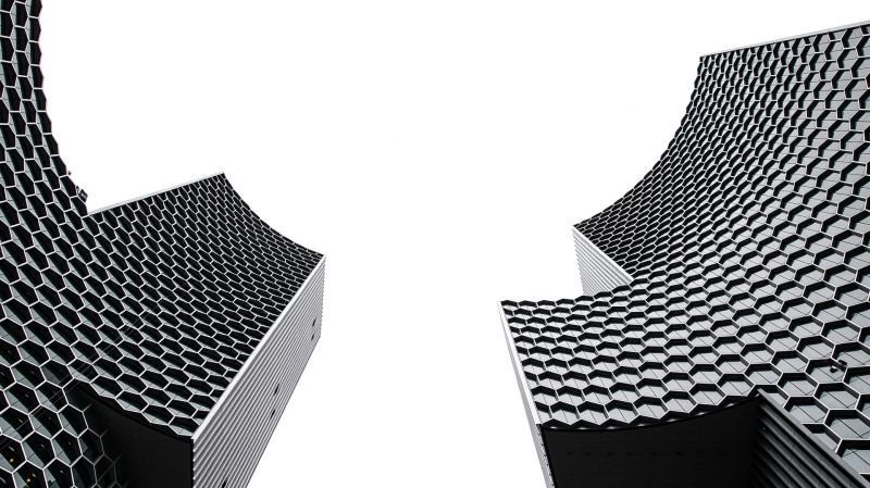
Laboratory ratings describe a defined test specimen. Actual facade performance depends on the interaction of every component, connection, and interface.
Laboratory sound insulation tests evaluate a defined specimen under controlled conditions. A completed facade, however, is a much more complicated assembly.
It includes panel-to-panel joints, perimeter seals, metal subframes, mechanical brackets, window interfaces, slab edges, and connections to adjacent building elements.
These components interact in different ways. Some allow airborne sound to pass through small openings. Others transmit vibration through solid materials. Some cavities can amplify sound at particular frequencies.
This distinction is important because sound does not always follow the direct path through the center of a panel.
For example, a well-insulated cladding panel may be installed alongside a window system with weaker acoustic performance. Noise can then enter through the window or its perimeter connection. Similarly, sound may travel around the panel through an inadequately sealed joint or a structural connection.
In engineering terms, these are different transmission paths, and each requires a different control measure.
Joint geometry, sealant performance, and installation continuity all influence whether sound can bypass the intended panel construction.
Airborne sound requires no large opening to pass through a facade. Even relatively narrow gaps can reduce the effectiveness of an otherwise well-insulated assembly.
Panel joints are particularly important because facade systems must accommodate manufacturing tolerances, installation deviations, and thermal movement.
Metal panels expand and contract as temperatures change. Buildings also experience structural movement, including floor deflection and differential movement between facade components. If joints are designed without sufficient movement capacity, sealants may become overstretched, compressed, or detached.
A joint that initially appears airtight may gradually develop discontinuities.
The acoustic consequence is straightforward: sound can pass through these openings without having to travel through the full panel construction. This is a form of flanking or leakage transmission that can undermine the expected performance of the facade.
Effective acoustic sealing therefore requires more than applying sealant to visible gaps.
The joint must accommodate the expected movement without losing its sealing function.
The sealant must be suitable for the adjoining materials and the expected environmental exposure.
Incorrect joint dimensions can affect the sealant's ability to deform and maintain adhesion.
Sealing must remain continuous at corners, intersections, panel edges, and transitions to windows or other facade elements.
Weather-resistant joints must also manage water. Acoustic sealing details should not block drainage paths or compromise pressure-equalized rain-screen principles.
This creates an important coordination challenge. A facade joint must accommodate movement, resist weather penetration, and limit unwanted sound transmission at the same time.
Solid mechanical connections can transfer vibration between facade components, creating sound transmission paths that bypass the intended acoustic separation.
Not all sound enters through air gaps. Some travels through the solid components of a building.
When sound excites a facade panel, the panel vibrates. If it is rigidly connected to metal brackets, rails, or structural members, part of that vibration can be transferred into the supporting structure.
A similar problem occurs when two otherwise separated facade layers are connected by continuous rigid components. These connections can act as mechanical bridges, allowing vibration to bypass the intended acoustic separation.
The result is often described as an acoustic bridge or, more specifically, a structural flanking path.
The issue is not limited to the type of bracket used. Connection stiffness, contact area, fastener arrangement, supporting member geometry, and the dynamic behavior of the materials all influence vibration transfer.
In some assemblies, resilient isolation components can reduce the transmission of vibration between connected elements. However, their effectiveness depends on the applied load, stiffness, damping characteristics, frequency range, and long-term durability.
Isolation must also be coordinated with structural requirements. A bracket cannot be made flexible without considering its ability to resist wind pressure, suction, dead load, and thermal movement.
This is why acoustic isolation should be designed into the connection detail rather than added as an afterthought.
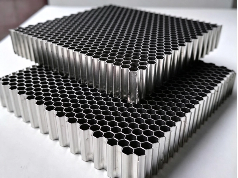
The air space between facade layers influences acoustic behavior and should be considered as part of the complete assembly.
An air cavity between facade layers can improve sound insulation, but it can also introduce acoustic behavior that needs careful control.
In a double-leaf construction, two panels separated by an enclosed air space form a mass-air-mass system. The two panel masses interact with the stiffness of the air trapped between them.
This system has a characteristic resonance frequency. Near this frequency, the two leaves may move in a way that increases sound transmission rather than reducing it.
The resonance behavior depends on several factors:
Surface mass of each panel.
Depth of the air cavity.
Air properties and cavity configuration.
Mechanical connections between the two leaves.
Damping and absorptive treatment within the cavity.
A deeper cavity can shift the mass-air-mass resonance to a lower frequency, but it does not automatically eliminate the problem. Rigid connections between the layers may still create flanking paths.
Porous absorptive materials can help reduce sound reflections inside the cavity and improve its acoustic behavior. However, absorption and sound insulation are different functions. Absorptive materials do not replace the need for adequate panel mass, separation, and connection design.
For facade engineers, the important point is that an air gap should not be treated as an empty space with no acoustic consequences. Its dimensions and surrounding construction are part of the overall sound transmission system.
Different sound mechanisms require different evaluation methods and engineering responses.
Another common source of confusion is treating all building noise as the same acoustic problem.
In reality, different sound transmission mechanisms require different evaluation methods.
Airborne sound travels through the air and excites building elements. Examples include road traffic, aircraft, voices, and machinery noise. Facade sound insulation ratings such as Rw are used to evaluate resistance to this type of transmission.
Impact sound begins with a physical impact on a building element, such as footsteps on a floor or objects striking a surface. It is especially relevant to floor and ceiling assemblies and is not directly represented by the Rw rating of a facade panel.
Structure-borne sound travels through solid building components as vibration. Mechanical equipment, rigid connections, and vibration transmitted through supporting structures can contribute to this type of noise.
These mechanisms can overlap. For example, vibration from mechanical equipment may travel through a structural frame and then cause another surface to radiate airborne sound into a room.
Identifying the original transmission path is essential. Adding thicker facade panels will not necessarily solve noise caused by a rigid mechanical connection or a poorly isolated piece of equipment.
Effective sound control requires coordination across panels, joints, cavities, supporting structures, and installation procedures.
Reducing unwanted sound transmission requires coordinated design across panels, joints, cavities, and supporting structures.
Several engineering measures can help.
Use continuous sealing details. Panel joints, perimeter connections, and transitions between different facade materials should be detailed to maintain airtightness while accommodating expected movement.
Control rigid sound bridges. Where appropriate, resilient isolation components can be introduced at connections. Their structural capacity and dynamic behavior must be verified rather than assumed.
Coordinate cavity dimensions. The depth and configuration of air cavities should be considered alongside panel mass, resonance behavior, and the location of mechanical connections.
Separate acoustic and drainage functions carefully. Rain-screen facades often rely on drainage and pressure management. Sealing details must prevent unwanted sound leakage without creating water traps or blocking drainage routes.
Account for structural movement. Wind deflection, thermal expansion, slab movement, and installation tolerances can all affect joint continuity and connection behavior.
Test representative assemblies. Testing an isolated panel is not enough when the main risks lie at joints and interfaces. Where acoustic requirements are demanding, representative assemblies should include the actual panel construction, supporting frame, connections, and perimeter details.
Site inspection is equally important. Sealant discontinuities, incorrectly installed isolation pads, missing components, and unplanned rigid contacts can all change the acoustic behavior of the completed facade.
Acoustic coordination should begin before fabrication, with clear responsibilities across design, procurement, construction, and inspection.
Architects, facade consultants, contractors, and procurement teams should assess acoustic details before fabrication and installation begin.
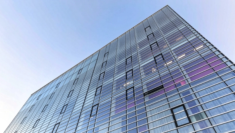
The answers should be reflected in coordinated drawings, material specifications, installation instructions, and inspection procedures.
For projects with demanding performance requirements, the proposed materials and connection details need to be compatible with the wider facade design.
Panel construction, supporting frames, connection details, fire performance, and weather protection must be coordinated as part of one facade system.
These acoustic challenges are closely connected to broader facade engineering requirements. Panel construction, supporting frames, connection details, fire performance, and weather protection must be coordinated rather than evaluated separately.
Established in 1995, WILLSTRONG® works with aluminum composite panels, fire-resistant composite materials, and aluminum honeycomb systems for architectural facade applications.
For projects involving lightweight facade construction, WILLSTRONG® facade systems can be considered as part of an assembly that coordinates panel configuration with supporting structures and installation details.
Another example from WILLSTRONG's project portfolio is the Hainan Guotou Eco-Environment Building, featuring approximately 9,150 m² of aluminum composite panel curtain wall.
Large-scale facade applications require coordinated consideration of panel layout, supporting structures, joints, and installation details. These interfaces are also important in acoustic design, where gaps or rigid connections may create unintended sound transmission paths.
The project illustrates the importance of treating facade materials and their supporting details as an integrated system, rather than evaluating panels in isolation.
For projects where sound insulation is critical, the final design should be based on the actual transmission paths, representative acoustic test data, and the construction details used on site. Panel selection, joint design, mechanical connections, and cavity configuration should all be reviewed as parts of the same system.
The acoustic performance of a completed facade depends on how effectively the entire assembly manages sound transmission.
A facade does not transmit sound through its panels alone. Joints, rigid connections, cavities, and interfaces can create alternative paths that reduce the performance expected from laboratory-tested materials.
The engineering response is not always to specify a heavier or thicker panel. It is to identify how sound travels through the complete assembly and address the weak points at the appropriate locations.