 Arabic
 Spain
 Germany
 France
 Japan
 Portuguese
 Russian
 Chinese
 Thailand
 Vietnam
 Indonesia
 India
News
The pioneer in facade solutions


A facade can remain visually intact under strong wind and still experience a serious engineering problem.
Occupants may hear whistling sounds around panel joints. Metal cladding may produce intermittent rattling. Supporting components may vibrate repeatedly, even when there is no obvious structural damage.
These symptoms are sometimes treated as minor acoustic or installation issues. However, they can indicate a more fundamental interaction between airflow, structural stiffness and connection behavior.
Wind does not always act as a steady pressure on a building. As air moves around corners, edges and projecting elements, it creates changing pressure patterns and aerodynamic forces. Under certain conditions, these forces can excite facade components at or near their natural frequencies, producing noticeable vibration or resonance.
The important question is not simply whether a facade can withstand a specified wind pressure. It is whether the facade system can remain dynamically stable when exposed to changing airflow over time.
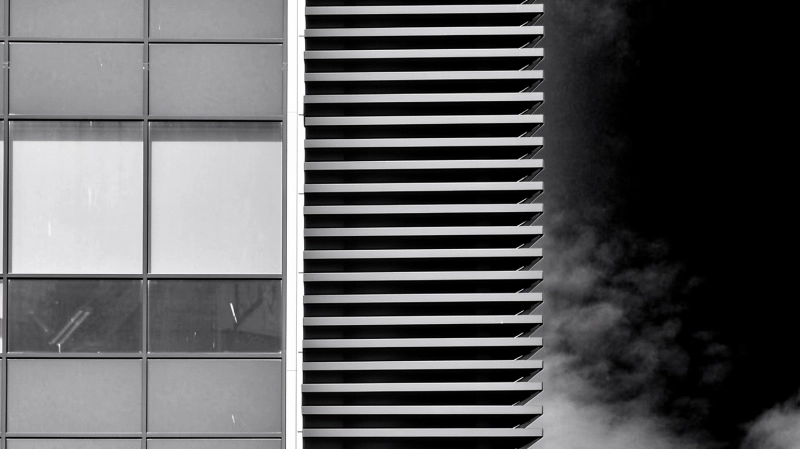
Wind-induced vibration occurs when fluctuating aerodynamic forces act on a structure or one of its components.
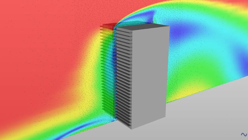
When wind approaches a building, airflow changes direction and velocity as it encounters the facade, corners, parapets and other geometric features. These changes create areas of positive pressure, suction and turbulent flow.
Unlike a constant static load, aerodynamic forces can vary over short periods. The resulting pressure fluctuations may cause facade panels, supporting profiles and connection components to move repeatedly.
Several mechanisms contribute to this behavior.
Turbulent airflow produces irregular pressure fluctuations across the facade. These changing forces can excite structural components and cause them to vibrate.
When airflow passes around an edge or a bluff body, vortices may form and detach alternately from opposite sides. This process creates periodic variations in aerodynamic forces.
If the frequency of an aerodynamic excitation approaches the natural frequency of a facade component or supporting structure, the vibration response may increase significantly.
These mechanisms are not identical, but they can interact. A facade component exposed to turbulent airflow may also experience vortex-related excitation, while its response depends on its stiffness, mass, damping and boundary conditions.
This is why wind-induced vibration cannot be assessed simply by checking the maximum wind pressure applied to a panel.
A facade must be evaluated not only for the magnitude of the applied wind load, but also for how fluctuating aerodynamic forces interact with the natural dynamic characteristics of its components.
Vortex shedding is particularly relevant when discussing wind-related vibration around architectural edges, exposed profiles and projecting facade elements.
As air flows past an obstacle, the boundary layer separates from its surface. Under suitable flow conditions, vortices are released alternately from different sides, creating a repeating pattern in the wake.
This process is associated with a characteristic shedding frequency.
A simplified relationship is:
f = St × U / D
Where:
represents the vortex shedding frequency.
is the Strouhal number, which depends on the flow and geometric characteristics.
is the characteristic airflow velocity.
is a representative dimension of the obstacle.
The equation illustrates an important point: changes in wind speed or component geometry can change the frequency of aerodynamic excitation.
Every structural component also has natural frequencies determined by its mass, stiffness, geometry and support conditions.
When the vortex shedding frequency approaches a natural frequency, the component may experience increased vibration. This is commonly described as vortex-induced resonance or vortex-induced vibration, depending on the specific response.
The consequences depend on the component and exposure conditions.
A relatively small movement may produce audible rattling or repeated contact between adjoining parts.
In more demanding situations, sustained cyclic vibration can place additional stress on fasteners, brackets and supporting connections.
Not every facade component will experience vortex-induced resonance. The actual risk depends on its geometry, aerodynamic exposure, structural characteristics and operating wind conditions.
The dynamic response of a facade depends on more than its material strength.
A panel, aluminum profile or mechanical connection has a natural frequency. This describes the frequency at which the component tends to vibrate when disturbed.
Natural frequency is influenced mainly by three factors:
A heavier component generally has a lower natural frequency when stiffness and boundary conditions remain unchanged.
The mass of a facade assembly therefore matters. Panel weight, supporting profiles, brackets and connected components all contribute to the dynamic characteristics of the system.
Greater structural stiffness generally increases natural frequency for a component with unchanged mass.
Panel thickness, material properties, core configuration and support spacing all influence stiffness.
For composite panels, the relationship between the face sheets and core is particularly important. The structural contribution of each layer depends on the panel configuration and how effectively the layers work together.
Damping describes how vibration energy is dissipated within a system.
Connections, material interfaces and dedicated damping components can influence the amount of energy lost during vibration.
A structure with appropriate damping may experience a lower vibration response than an otherwise similar structure with limited damping.
This leads to an important engineering consideration: increasing panel thickness or stiffness does not automatically eliminate wind-induced vibration.
It may shift the natural frequency away from one excitation range, but it does not necessarily remove the aerodynamic force, improve damping or correct an unstable connection.
If the supporting framework remains flexible or the airflow continues to generate periodic excitation, the vibration problem may simply move to another component or frequency range.
The objective should therefore be to evaluate mass, stiffness, damping and aerodynamic exposure together.
Not every wind-related noise problem is caused by structural resonance.
Sometimes, the sound originates from airflow interacting with relatively small facade details.
Narrow gaps, exposed edges, drainage openings, perforations and irregular panel joints can alter local airflow. Under certain conditions, air passing through or around these features creates pressure fluctuations that generate audible tones or broadband noise.
Three common situations deserve attention.
Air passing through a narrow opening may create periodic pressure fluctuations. Depending on the opening geometry and airflow velocity, this can produce a whistle-like sound.
If panels, covers or supporting components have excessive clearance, fluctuating wind forces may cause repeated contact between adjoining parts.
Loose fasteners and poorly restrained accessories can also produce intermittent noise.
A panel or profile responding to fluctuating aerodynamic forces may produce low-frequency vibration that becomes audible through the building structure or surrounding materials.
The source of the sound is not always located where occupants hear it. Vibrations can travel through connected profiles and brackets before becoming noticeable elsewhere.
For this reason, adding sealant to a noisy joint or tightening one visible fastener may not resolve the underlying problem.
Facade components do not operate independently. Their structural performance depends on how forces move through the complete assembly.
A panel transfers aerodynamic forces to supporting profiles, which then distribute those forces through brackets and mechanical connections into the primary building structure.
If one component has insufficient stiffness or inadequate restraint, it may become the dominant source of movement.
For example, a relatively rigid panel installed on a flexible subframe may still experience noticeable vibration. Similarly, a well-designed supporting profile cannot compensate for a connection that allows unintended movement.
Several engineering measures can help reduce these risks.
The position and spacing of supporting profiles influence both panel stiffness and vibration behavior. Reducing unsupported spans may improve resistance to local bending and movement, subject to the overall system design.
Fasteners and brackets should provide the required structural restraint without introducing unintended looseness or excessive local stress.
Corners, panel edges and exposed facade zones may require different support arrangements from central facade areas because their aerodynamic exposure can be different.
Connection details must also account for thermal movement and construction tolerances. A connection that is too rigid in the wrong direction may transfer additional stress, while an inadequately restrained connection may allow repeated movement.
Local reinforcement should be based on structural analysis rather than applied uniformly without considering the actual load conditions.
Where vibration response is significant, suitable damping measures or revised connection configurations may help reduce the amplitude of movement.
The appropriate solution depends on the vibration mechanism and must be verified within the complete assembly.
Repeated wind-load cycles can influence mechanical connections and supporting components over the service life of a facade.
A facade may experience thousands of changing wind-load cycles during its service life.
Although an individual pressure fluctuation may not cause immediate damage, repeated movement can gradually affect mechanical connections and supporting components.
This is where structural fatigue becomes relevant.
Fasteners may experience repeated stress variations. Brackets can be subjected to cyclic bending, while local contact between components may cause wear or changes in connection behavior.
Not every instance of vibration leads to fatigue failure. The actual fatigue risk depends on stress range, cycle count, material properties, connection details and environmental conditions.
Nevertheless, recurring noise or movement should not automatically be dismissed as a cosmetic issue.
Inspection should focus on the entire load path, including panel supports, brackets, fasteners and anchoring points.
Reducing wind-induced vibration requires an understanding of both aerodynamic forces and the dynamic response of facade components.
For projects with significant exposure or unusual architectural geometry, engineering teams may need to consider additional analysis methods.
These can include:
Wind tunnel testing can help evaluate pressure distributions and aerodynamic effects around complex building geometries. Depending on the project, specialized testing may also be used to investigate dynamic wind response.
Structural modal analysis helps identify natural frequencies and vibration modes of panels, supporting profiles or larger facade assemblies.
Detailed reviews of brackets, fasteners and supporting structures help identify locations where movement or stress concentrations may develop.
When vibration or noise is reported after installation, inspections and targeted measurements can help distinguish aerodynamic excitation from loose connections, installation defects or other sources.
The most effective approach is to connect these findings with actual fabrication and installation details.
A calculation based on idealized support conditions may not represent a facade installed with different fixing positions, tolerances or connection restraints.
Engineering verification must therefore reflect the system that will actually be built.
An international landmark project associated with WILLSTRONG®'s facade applications.
Paris Charles de Gaulle Airport is among the international landmark projects associated with WILLSTRONG®'s facade applications.
Airport buildings provide an interesting context for facade engineering because their architectural requirements often involve extensive building envelopes, large public spaces and complex interfaces between different structural and facade components.
In such environments, facade design must consider more than the appearance of the exterior surface. Panel configuration, supporting structures, connection details, environmental exposure and installation coordination all contribute to the performance of the building envelope.
The airport project provides a reference for WILLSTRONG®'s participation in large-scale architectural applications.
However, the available project information does not establish specific wind-induced vibration measurements, vortex shedding analysis or acoustic test results for this project. It is therefore used here as an application reference rather than evidence of a particular dynamic performance rating.
The broader engineering lesson remains relevant: facade materials must be considered as part of a complete structural and architectural system, particularly when used in large public buildings.
Procurement teams should look beyond standard material specifications when projects involve strong wind exposure, exposed edges or complex facade geometry.
When a project involves strong wind exposure, exposed edges or complex facade geometry, procurement teams should look beyond standard material specifications.
Several questions can help assess a supplier's technical capability.
Are panel thickness, core structure, face-sheet construction and mechanical properties clearly documented?
Can panel dimensions, edge details and fixing positions be maintained according to the approved drawings?
Can the supplier coordinate panel processing with the supporting profiles, brackets and fastening arrangements?
Are relevant material and component test reports available? Can the supplier provide technical information needed for project-specific structural verification?
Can potential fabrication conflicts and connection issues be identified before manufacturing begins?
A supplier does not replace the structural engineer or facade consultant. However, accurate technical documentation and coordinated fabrication are important parts of turning an engineering design into a functioning facade.
Material selection should reflect the relationship between panel construction, supporting components and project-specific design conditions.
Established in 1995, WILLSTRONG® works with aluminum composite panels, fire-resistant composite materials and aluminum honeycomb systems for architectural facade applications.
These material categories have different structural configurations and application characteristics. Their selection should reflect the required panel dimensions, weight, stiffness, support arrangement and project-specific design conditions.
For facade systems exposed to changing wind conditions, the relationship between panel construction and supporting components deserves particular attention.
WILLSTRONG® approaches facade applications through the principle of "Crafting with Quality, Making for Excellence," with an emphasis on coordinating material specifications and fabrication details with actual project requirements.
For engineers and project teams, the priority is not simply to select the stiffest panel available. It is to ensure that the panel, subframe, connections and building structure work together under both static and dynamic loading conditions.
Wind-induced vibration is ultimately a system problem. It cannot always be solved by changing one material specification or strengthening one isolated component.
Facade engineering must account for how the complete system responds when wind conditions change.
Good facade engineering does not simply resist wind pressure. It controls how the entire system moves when the wind changes.