 Arabic
 Spain
 Germany
 France
 Japan
 Portuguese
 Russian
 Chinese
 Thailand
 Vietnam
 Indonesia
 India
News
The pioneer in facade solutions


A facade can pass a water-tightness test and still leak during a severe storm.
A facade can pass a water-tightness test and still leak during a severe storm.
This is not necessarily a contradiction. A conventional water test may demonstrate that a facade resists water penetration under a defined test pressure and spray condition. However, real weather introduces changing wind pressure, fluctuating airflow, different rain directions and variations in pressure across the building envelope.
When wind-driven rain strikes a facade, water does not simply fall vertically onto its surface. Wind can force water toward panel joints, window interfaces, corner details and drainage openings. If the pressure difference across the facade is not properly managed, even relatively small construction gaps can become potential leakage paths.
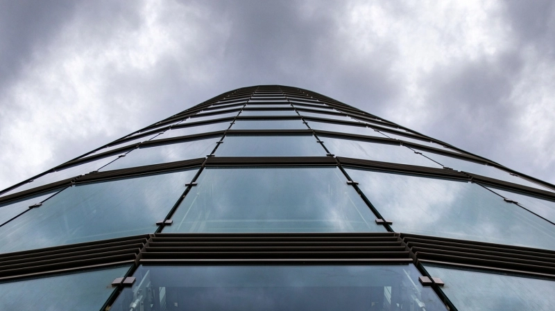
Understanding the difference between controlled laboratory conditions and changing weather exposure is essential when evaluating facade water resistance.
Static water-tightness testing provides an important way to evaluate facade performance. During testing, water is sprayed onto a representative facade specimen while a specified pressure difference is applied across it.
This helps determine whether water penetrates the assembly under defined conditions.
However, static testing and actual storm exposure are not identical.
In real conditions, wind speed and direction can change rapidly. Gusts may create temporary pressure increases, while surrounding buildings, corners and architectural projections can alter local airflow. Rain may also strike the facade at different angles rather than falling evenly across the surface.
Dynamic water-tightness testing introduces controlled changes in pressure to better represent fluctuating wind conditions. Depending on the applicable test method, pressure may be applied in cycles or through other defined variations while water is continuously sprayed onto the specimen.
The difference matters because a joint that remains stable under a relatively constant pressure may respond differently when the pressure repeatedly increases and decreases.
For example, pressure fluctuations can affect flexible gaskets, sealant interfaces and drainage cavities. Small movements at connections may also change the way water enters or leaves a joint.
A single successful test result should therefore be interpreted within the conditions of the test. It does not automatically demonstrate performance under every possible combination of wind speed, rain intensity and installation condition.
Water penetration generally requires two conditions: a pathway through the facade and a driving force that moves water through it.
Water penetration generally requires a pathway and a driving force.
In facade systems, these conditions can occur together at panel joints, perimeter seals, mechanical connections and interfaces between different building materials.
Wind-driven rain creates a water film on the exterior surface. When a pressure difference exists between the outside and inside of the facade, water can be pushed through available openings.
Three mechanisms are particularly relevant.
Air pressure outside the building may be higher or lower than the pressure inside a facade cavity or occupied space. This difference can drive air and water through discontinuities in the building envelope.
The greater the effective pressure difference across an opening, the greater the potential for forced water penetration, assuming water is present at that location.
Narrow gaps between adjoining materials can allow water to move through capillary action. This is particularly relevant where joint geometry creates small continuous spaces between panel edges, gaskets or adjacent components.
Even when the opening appears insignificant, its geometry can support water movement.
Water also moves downward along the facade surface. If horizontal joints, ledges or panel interfaces do not provide appropriate drainage, water may accumulate around vulnerable details.
These mechanisms often interact rather than acting independently.
Water can enter through an upper joint, travel along an internal surface and eventually appear at a lower connection.
Identifying the visible leak is therefore not always enough. The actual entry pathway must be investigated.
Wind direction and building geometry create different pressure conditions, each of which affects joints, gaskets, sealants and internal facade cavities.
Facade joints are exposed to different pressure conditions depending on wind direction and building geometry.
Under positive exterior pressure, air and water may be driven toward the interior. Sealants and gaskets must maintain their intended contact and deformation characteristics to limit penetration.
Under negative pressure, suction can pull air outward through openings. It can also affect flexible joint components and change the pressure relationship between different facade cavities.
Repeated pressure changes introduce additional demands.
Sealants are expected to accommodate joint movement while maintaining adhesion and cohesion. If the joint is incorrectly sized, the substrate is poorly prepared or the sealant is exposed to movement beyond its design capability, cracking or separation may occur.
Gaskets also depend on correct compression. Insufficient compression can leave gaps, while excessive compression may create installation difficulties or reduce the ability of the gasket to accommodate movement as intended.
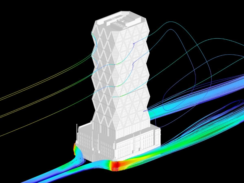
A facade cannot rely on the assumption that every drop of water will always be stopped at the outermost seal. Some systems are designed to manage limited water penetration through designated drainage chambers and secondary barriers.
The objective is to prevent water from reaching sensitive interior areas, even when the outer layer is exposed to severe weather.
Pressure-equalized rain-screen principles provide a different approach to managing water within modern facade assemblies.
One of the important developments in modern facade engineering is the use of pressure-equalized rain-screen principles.
Traditional approaches often relied heavily on exterior sealants to prevent water from entering through every joint. While properly designed and installed sealants remain important, relying on a single external barrier creates challenges over the long term.
Sealants age, joints move and building materials expand or contract under changing temperatures. If the exterior seal fails, water may enter the cavity with no effective route for removal.
Pressure-equalized facade systems take a different approach.
They use a ventilated or compartmentalized cavity behind the outer cladding, together with controlled openings and an internal air barrier.
The principle is relatively straightforward.
When wind pressure acts on the outer surface, air can enter the designated cavity through carefully designed openings.
This helps the pressure within the cavity approach the external pressure, reducing the pressure difference across the outer cladding joints.
With a smaller pressure difference, there is less force available to drive water through those joints.
However, pressure equalization does not mean that all water penetration is eliminated. Rain can still enter the outer cavity through wind action, surface runoff or other mechanisms.
This is why pressure management must be combined with drainage.
The cavity needs an appropriate route for collected water to move outward, while the inner air barrier helps prevent uncontrolled air and water movement into the building.
Compartmentalization is also important. If the cavity is too large or interconnected without appropriate control, pressure may not equalize effectively across the entire facade area.
The design must therefore consider cavity dimensions, opening positions, internal barriers and the geometry of individual facade zones.
Pressure equalization alone cannot guarantee reliable water management. Construction details and installation accuracy remain essential.
Even a well-conceived pressure-equalization strategy can fail if its construction details are poorly executed.
Drainage is not simply a matter of providing openings at the bottom of a facade. Water must have a continuous, unobstructed route from the collection area to the exterior.
Several details deserve particular attention.
Openings must be positioned and sized according to the system design. They should allow the intended airflow and drainage without creating uncontrolled paths for water to enter sensitive areas.
Debris, excessive sealant and construction residues can obstruct these openings. A drainage detail that works on a drawing may become ineffective if its outlet is blocked during installation.
Joint width must account for manufacturing tolerances, installation variation, thermal expansion and expected structural movement.
If a joint is too narrow, adjoining panels may come into contact as temperatures change. If it is too wide or uneven, the gasket or sealant may not perform within its intended working range.
Joint dimensions are therefore both an architectural and an engineering consideration.
Misaligned panels, uneven supporting profiles and inconsistent fixing positions can change the designed joint geometry.
Small deviations may accumulate across a large facade. This can create inconsistent gasket compression, interrupted drainage slopes and local water-trapping points.
The most vulnerable locations are often where different facade components meet. These include panel-to-window interfaces, parapets, corners, slab edges and transitions between different cladding materials.
Each interface needs a clearly defined water-management strategy rather than relying on sealant as the only protection.
Sealants remain important, but reliable facade waterproofing requires a coordinated system that accounts for movement, pressure, drainage and long-term exposure.
Sealant technology has developed considerably, but the fundamental engineering challenge remains: a sealant joint is a moving component exposed to environmental conditions.
Temperature changes cause materials to expand and contract. Wind pressure creates movement, while building settlement and interstory drift can change joint dimensions.
Ultraviolet exposure, moisture and long-term aging can also influence sealant performance.
A facade that depends entirely on continuous external sealing may therefore require increasingly demanding maintenance over its service life.
These functions work together.
It needs to control where water can go, reduce the forces that drive it inward and provide a reliable route for removal.
This approach is particularly important for large commercial buildings, where extensive facade areas contain numerous joints and interfaces.
A commercial facade project demonstrating the application of perforated aluminum composite panels across an extensive exterior surface.
Poland · Completed 2012
Galeria Korona Kielce in Poland provides a real example of WILLSTRONG®'s perforated aluminum composite panel application in commercial facade construction.
Completed in 2012, the project features approximately 14,000 square meters of perforated aluminum composite panels. The facade integrates the perforated panel arrangement with architectural lighting, creating different visual effects during the day and at night.
From an engineering perspective, a large perforated facade introduces considerations beyond the appearance of the individual panels.
Panel dimensions, opening patterns, fixing positions and supporting structures must be coordinated to maintain consistency across an extensive facade surface.
The project also provides a useful opportunity to distinguish between the functions of an outer architectural screen and those of the primary weather-resistant building envelope.
Perforated panels may allow airflow and visual transparency, but they should not automatically be treated as the building's primary water barrier. Their role must be understood in relation to the backing wall or secondary facade system behind them.
It is therefore more appropriate to use the project as an example of large-scale facade material application rather than as evidence of a particular water-tightness rating.
Selecting a facade supplier for demanding weather conditions requires evaluating the complete facade assembly rather than relying on material specifications alone.
When selecting a facade supplier for projects exposed to strong winds and heavy rainfall, material specifications alone are not enough.
The technical evaluation should include several practical questions.
Can the supplier support detailed fabrication drawings?
Are the panel joints compatible with the proposed water-management strategy?
Can the supplier maintain fabrication accuracy?
Panel dimensions, joint positions, folded edges and fixing details need to match the intended facade design.
The relationship between exterior joints, cavity dimensions, drainage openings and the inner air barrier should be clearly understood.
Consistent panel dimensions and edge processing help reduce installation deviations that may affect joint geometry and drainage.
Water-tightness testing should reflect the intended facade configuration, including representative joints, interfaces and pressure conditions. Air leakage and water penetration should also be evaluated as related but distinct performance requirements.
Early coordination between the facade designer, material supplier, system fabricator and installer can prevent many problems that would otherwise become difficult to correct on site.
These questions shift procurement away from simply comparing panel materials and toward evaluating the performance of the complete facade assembly.
Material manufacturing, panel processing and coordinated technical details help turn the water-management strategy into a buildable facade.
Established in 1995, WILLSTRONG® specializes in aluminum composite panels, fire-resistant composite materials and aluminum honeycomb systems for architectural facade applications.
Its experience with projects such as Galeria Korona Kielce provides a practical reference for understanding how panel fabrication, perforation patterns and facade configuration interact in large-scale commercial architecture.
For projects involving wind-driven rain, the selected facade material must be considered alongside the supporting system, joint design, drainage arrangement and installation requirements.
A material supplier's role is not to replace the facade engineer responsible for system design. Rather, accurate product information, coordinated fabrication details and consistent panel processing help the project team translate its water-management strategy into a buildable facade.
WILLSTRONG® approaches facade materials through the principle of "Crafting with Quality, Making for Excellence," with attention to how product specifications and manufacturing details support the intended architectural application.
It is defined by how effectively the entire system controls pressure, manages water movement and accommodates change throughout its service life.
Reliable water resistance depends on pressure control, drainage, joint design and coordinated installation.
A reliable facade does more than simply keep water out.
It controls how water enters, moves through and exits the system, ensuring that any water reaching the internal drainage cavity can be safely discharged.
This requires carefully coordinated joint design, pressure management and drainage paths.
By giving water a clear route out, the facade reduces the risk of accumulation, leakage and long-term material damage.