 Arabic
 Spain
 Germany
 France
 Japan
 Portuguese
 Russian
 Chinese
 Thailand
 Vietnam
 Indonesia
 India
News
The pioneer in facade solutions


Wind resistance is not determined by the strength of a single panel. It depends on how the entire facade system responds to changing wind conditions, transfers loads through its connections and accommodates movement within the building structure.
point in the building envelope. Excessive deflection, loosened connections, damaged joints and repeated structural movement may occur even when the panel itself has not fractured.
This raises an important question in facade engineering: Is meeting the required wind pressure rating enough to ensure structural safety?
In practice, wind load resistance is not determined by the strength of a single panel. It depends on how the entire facade system responds to changing wind conditions, transfers loads through its connections and accommodates movement within the building structure.
For large public buildings, stadiums and high-rise developments, this distinction is particularly important. A reliable facade must do more than resist a single pressure value. It must maintain its structural integrity throughout repeated wind loading and changing environmental conditions.

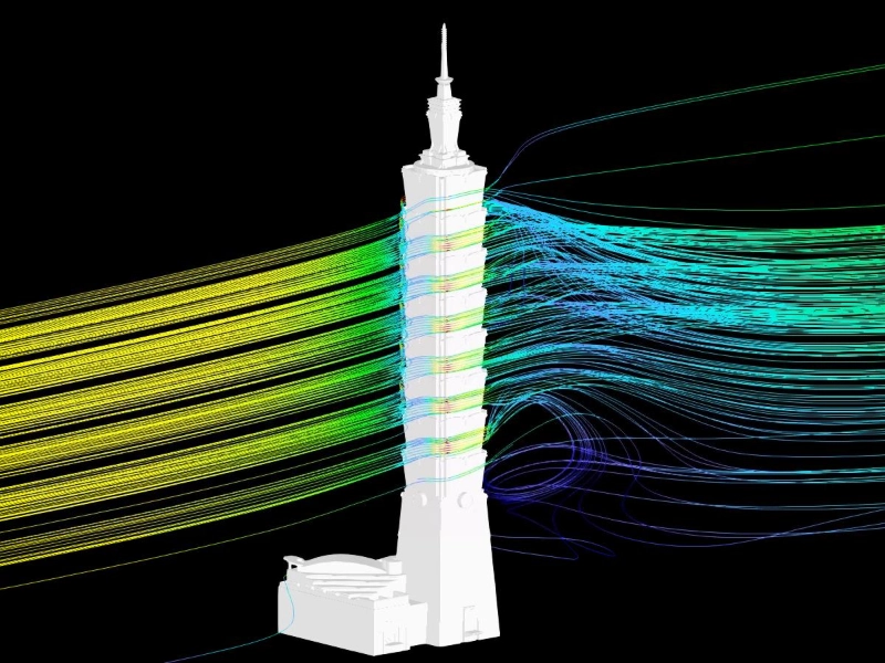
Wind pressure is influenced by the building's height, geometry, surroundings and local aerodynamic conditions. Panel specifications should follow the actual building exposure.
Wind pressure acting on a facade is influenced by several factors, including basic wind speed, building height, surrounding terrain, building geometry and local aerodynamic effects.
Basic wind pressure provides an important starting point for structural calculations. However, it is not necessarily the actual pressure experienced at every point on a building.
As wind moves over a structure, its speed and pressure distribution change. Buildings located in open terrain may experience different wind exposure from those surrounded by other structures. At greater heights, wind speeds and exposure conditions can also become more demanding.
Gust effects introduce another consideration. Unlike steady wind, gusts produce short-duration changes in wind speed and pressure. The gust factor or the corresponding dynamic provisions in the applicable design code account for these effects when determining design wind actions.
Facade engineers must also consider local pressure coefficients. Corners, roof edges and building recesses can experience different pressure distributions from central facade areas. Local suction may be particularly significant around exposed edges.
Consequently, two facade panels installed on the same building may require different design considerations depending on their location.
A practical wind load design process therefore begins with the building's exposure and geometry before moving to individual panel specifications.
Wind pressure and suction act in opposite directions. Both require attention when evaluating panel behavior, fasteners and supporting connections.
Wind does not always push a facade inward.
Positive wind pressure generally acts toward the building, while negative pressure, commonly associated with suction, pulls the facade outward. Both conditions must be considered in facade structural design.
Under positive pressure, the panel transfers the applied load through its supports and connections toward the building structure. The panel may bend inward, placing demands on its face materials, core structure and supporting framework.
Under negative pressure, the load direction reverses. Fasteners, brackets and mechanical connections must resist pull-out forces and potential separation. A connection that performs adequately under inward pressure may behave differently when subjected to outward suction.
This is why checking only the panel's material strength is insufficient.
Wind pressure acts on the exposed facade surface.
The panel transfers the load to its supporting components.
Supporting components distribute the forces through brackets and connections.
Anchors transfer the loads into the primary building structure.
Any weak point along this path can affect overall performance.
In particular, connection failure may occur before visible damage develops in the panel itself. Fastener pull-out, local bearing failure, bracket deformation and inadequate edge distances are all potential concerns that require engineering attention.
Panel deformation depends on structural configuration, support spacing, material stiffness and boundary conditions.
Panel deflection is one of the most important indicators of facade performance under wind loading.
A panel may remain intact while bending beyond an acceptable serviceability limit. Excessive movement can affect joint widths, sealant performance, alignment and the appearance of the facade.
Several factors influence panel deflection.
Panel thickness affects bending stiffness, but thickness alone does not determine performance. Material properties, core configuration, face-sheet thickness and composite action also influence how a panel responds to pressure.
The distance between supporting points has a significant influence on deflection. A larger unsupported span generally produces greater bending under the same loading conditions.
The stiffness of the panel, its edge restraints and the way it is fixed to the subframe all influence the final deformation.
For example, aluminum composite panels and aluminum honeycomb panels use different structural configurations. Their bending behavior depends on the relationship between the facing materials, core and overall panel construction.
For a simplified beam model, deflection under a uniformly distributed load is proportional to the fourth power of the span, assuming the same boundary conditions and stiffness. Although actual facade panels may behave as plates rather than simple beams, the principle illustrates why support spacing must be carefully coordinated with panel dimensions.
A panel with sufficient material strength may still perform poorly if the support arrangement allows excessive movement.
Panel performance cannot be evaluated independently of supporting profiles, brackets, anchors and installation conditions.
Facade deflection is a system-level issue.
Even when the panel itself has adequate stiffness, the supporting aluminum profiles may bend under wind pressure. Brackets can deform, connections may develop movement, and anchors may experience concentrated forces.
These deformations accumulate along the load path.
For this reason, engineering reviews should consider at least four connected elements: the facade panel, supporting profiles, connection brackets and structural anchors.
The stiffness of each component must be compatible with the others. Increasing panel thickness without reviewing the supporting framework may not solve the actual problem.
Dead load also deserves attention. The weight of the facade system creates permanent forces in brackets and anchors, while wind introduces variable pressure and suction. The combined effects must be considered according to the relevant structural design requirements.
Installation tolerances add another layer of complexity. If the actual support positions differ from the drawings, the effective span and fixing conditions may change. Poor alignment can also introduce unintended stresses or uneven load distribution.
Engineering drawings should therefore be coordinated with fabrication dimensions, connection details and site installation procedures before production begins.
A facade must accommodate not only pressure on its surface but also movement transmitted through the building's structural frame.
Wind affects not only the facade surface but also the movement of the building itself.
When a building experiences lateral wind loading, its structural frame may sway. Adjacent floors can move relative to one another, creating interstory drift.
A rigidly connected facade that cannot accommodate this movement may experience additional stress at panel joints, brackets and anchors.
Potential consequences include cracked sealants, distorted connections, damaged panel edges and local stress concentrations.
This is why curtain wall and cladding connections often need carefully designed movement allowances. Fixed points and sliding or adjustable connections may be used to manage different movement requirements, depending on the system design.
Thermal expansion and construction tolerances must also be considered. Wind-induced movement is only one part of the total displacement that a facade system may need to accommodate.
Individual material tests and complete assembly tests provide different levels of engineering evidence.
A material or panel test can provide valuable information about strength, deformation and performance under specified conditions. However, it does not automatically demonstrate that an installed facade system will behave in the same way.
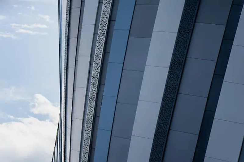
Individual panel testing typically focuses on the specimen and its defined support conditions. A complete facade assembly introduces additional variables, including:
System-level testing can evaluate how these components work together under specified pressure conditions.
For example, structural performance testing of a representative facade assembly can reveal excessive deflection, connection movement or local failure that may not be apparent from isolated material tests.
The test configuration must also reflect the intended application. Panel size, support spacing, fixing details and boundary conditions should be consistent with the project design as far as practicable.
For procurement teams, this distinction matters. A supplier's panel test report is useful, but it should not be treated as a substitute for project-specific structural calculations and complete system verification where required.
A real-world public building project provides context for evaluating aluminum composite panels within an actual facade application.
The Wuhan Sports Center Stadium provides a practical example of WILLSTRONG®'s aluminum composite panel application in a large-scale public building.
Completed in 2005, the project used WILLSTRONG® aluminum composite panels in its curtain wall application. The project record identifies aluminum composite panels as the facade material and documents their use in the stadium's exterior envelope.
A stadium facade presents a different set of coordination demands from a small-scale building envelope. Large facade areas, architectural geometry, panel layout and supporting arrangements all need to be considered together during design and installation.
Although the available project information does not provide specific wind pressure test results or structural calculations, the project illustrates an important principle: facade materials must be evaluated within the context of their actual application, dimensions and supporting systems.
The engineering question is not simply whether a panel can resist wind pressure. It is whether the selected panel configuration and its supporting details are appropriate for the intended facade arrangement.
Supplier evaluation should cover material documentation, fabrication accuracy, connection compatibility, testing and engineering coordination.
Wind load resistance should be part of the technical evaluation process from the beginning, rather than a specification checked only before delivery.
Architects, facade contractors and procurement teams can examine several aspects when assessing a supplier:
Are panel configurations, thicknesses, core structures and mechanical properties clearly documented?
Can the supplier maintain the dimensions, edge details and fixing positions required by the engineering drawings?
Are panel processing details coordinated with the proposed subframe, brackets and fastening methods?
Are test reports relevant to the actual panel configuration and intended application? Can the project team obtain system-level test support when required?
Can the supplier review drawings, identify potential fabrication conflicts and coordinate technical details before production?
These questions help distinguish between a supplier that only delivers facade materials and one that understands how those materials function within a complete building envelope.
Reliable facade performance depends on the coordination of material selection, manufacturing, supporting details and installation requirements.
Established in 1995, WILLSTRONG® works with aluminum composite panels, fire-resistant composite materials and aluminum honeycomb systems for architectural facade applications.
Its experience across facade projects, including the Wuhan Sports Center Stadium, provides a practical context for understanding the relationship between panel configuration, fabrication and facade application.
For wind-sensitive projects, the relevant consideration is how the selected material and its processing details fit into the overall engineering design.
Panel specifications, support arrangements, connection details and installation requirements should be coordinated rather than evaluated independently.
The company's approach, expressed through the principle "Crafting with Quality, Making for Excellence," places material quality and application requirements within the broader context of facade construction.
From wind pressure and panel deflection to connections and structural movement, every component contributes to facade reliability.
Good facade engineering is not simply about resisting the wind. It is about controlling how the entire system responds to it.
A reliable facade must transfer loads, control deformation and accommodate movement through a coordinated structural system.