 Arabic
 Spain
 Germany
 France
 Japan
 Portuguese
 Russian
 Chinese
 Thailand
 Vietnam
 Indonesia
 India
News
The pioneer in facade solutions


A facade can achieve a high sound insulation rating in a laboratory and still allow noticeable traffic noise into a building. Understanding Rw, C and Ctr helps engineers evaluate how facade systems respond to different environmental noise conditions.
A facade can achieve a high sound insulation rating in a laboratory and still allow noticeable traffic noise into a building. This is not necessarily a contradiction. It often means the acoustic performance has been evaluated using a number that does not fully represent the noise conditions the building actually faces.
For buildings near airports, highways, railway lines, or busy commercial districts, this distinction matters. Occupants do not experience sound as a single number. They hear engines, aircraft movements, tire noise, voices, and other sources, each with a different frequency distribution.
The weighted sound reduction index (Rw) provides a useful starting point, but it does not tell the whole story. To understand how a facade performs against different environmental noise sources, engineers also need to consider the spectrum adaptation terms C and Ctr.
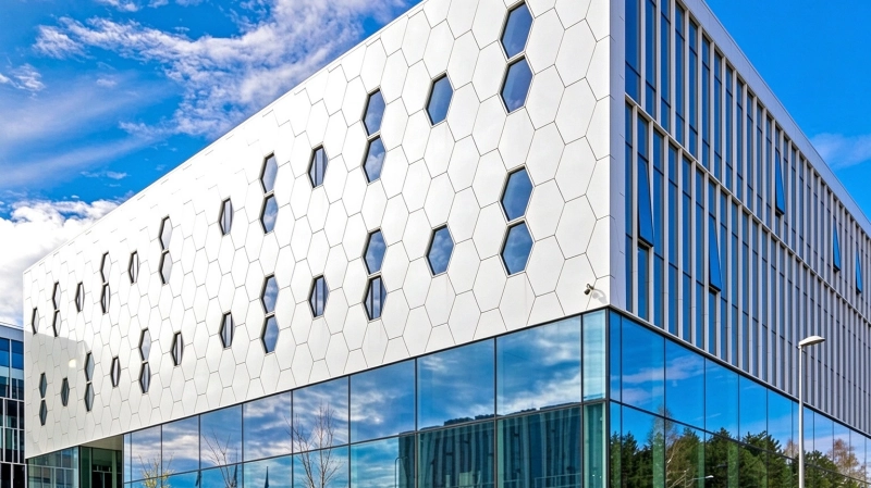
Acoustic performance should be evaluated in relation to the actual frequency characteristics of the surrounding noise environment, rather than relying on a single laboratory rating.
Understanding the weighted sound reduction index and how laboratory testing converts frequency-dependent measurements into a single rating.
Rw is a single-number rating used to describe the airborne sound insulation of a building element, such as a wall, panel, door, or window.
In laboratory testing, sound is generated on one side of a specimen, while the sound pressure levels on both sides are measured across a range of frequencies. The resulting sound reduction values are evaluated using a reference curve under ISO 717-1.
The standard rating commonly uses one-third-octave frequency bands from 100 Hz to 3,150 Hz. Rather than simply calculating an arithmetic average, the evaluation procedure shifts a reference curve against the measured results and determines the final weighted value.
This makes Rw useful when comparing building components under standardized conditions. However, reducing a frequency-dependent result to one number inevitably removes some detail.
Consider two facade panels with the same Rw rating. One may provide relatively balanced insulation across the tested frequency range.
The other may perform well at higher frequencies but show weaker insulation in certain lower-frequency bands.
Both can receive the same single-number rating, yet their responses to real-world noise may be noticeably different.
Spectrum adaptation terms provide additional information about how a building element responds to different types of environmental noise.
ISO 717-1 introduces two spectrum adaptation terms to account for the characteristics of different sound sources.
C is generally associated with a reference spectrum representing broadband noise, such as pink noise. It can be useful when considering indoor noise sources and sound insulation against a relatively broad frequency distribution.
Ctr is calculated using an A-weighted urban traffic noise spectrum. It is particularly relevant when evaluating building elements exposed to road traffic and other noise sources with a stronger low-frequency contribution.
For example, suppose a facade component has the following laboratory rating:
Its adjusted ratings are:
The difference is important. Although the component has an Rw rating of 45 dB, its adjusted rating for the urban traffic spectrum is 39 dB.
A more negative Ctr indicates that the component's insulation is less favorable when assessed against the traffic noise spectrum. This does not mean that every traffic noise source will be reduced by exactly 39 dB in a completed building. The actual indoor noise level also depends on the external spectrum, facade area, room conditions, flanking transmission, and other building elements.
The practical lesson is straightforward: when selecting facade systems for noisy locations, comparing Rw alone can lead to an incomplete assessment.
Low-frequency sound presents a particular challenge for lightweight facade construction, especially in buildings exposed to transport and urban noise.
Low-frequency sound presents a particular challenge for lightweight facade construction.
Road traffic is not simply a collection of high-frequency sounds. Heavy vehicles, engine operation, tire-road interaction, and acceleration can generate significant energy across lower frequency bands.
Aircraft noise introduces another complex spectrum. Aircraft engines, takeoff and landing operations, and changes in flight conditions produce sound that varies with frequency, distance, and time.
It may also travel through connected building elements, creating transmission paths that are not obvious when looking only at the external panel surface.
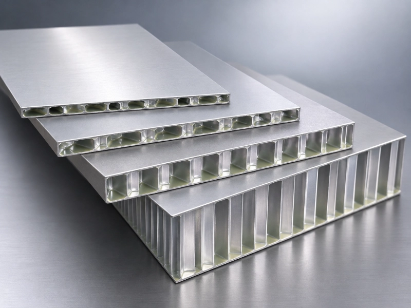
A lightweight panel can be structurally efficient while still requiring careful acoustic design. Its response depends on several factors:
Surface mass influences airborne sound insulation, while bending stiffness affects how the panel responds to vibration. Increasing stiffness alone does not guarantee better sound insulation.
Every panel has natural vibration characteristics. If incident sound energy interacts with these frequencies, sound transmission can increase within particular frequency bands.
At certain frequencies, bending waves in a panel can interact efficiently with airborne sound waves. This can create a reduction in sound insulation known as the coincidence effect.
Sound can travel through rigid connections and supporting components, bypassing the intended acoustic separation.
Multi-layer facade construction offers additional acoustic design possibilities, but the interaction between layers determines the final result.
A multi-layer facade can offer more design flexibility than a single panel, but the acoustic result depends on how its layers interact.
The first facade leaf contributes surface mass and stiffness to the overall acoustic system.
The air cavity between the two layers participates in the combined dynamic response and introduces a resonance frequency.
The second leaf works with the first panel and enclosed air to determine the acoustic behavior of the assembly.
In a double-skin or separated-panel construction, the air cavity between two layers can act as part of a mass-air-mass system. The two leaves and the enclosed air have a combined dynamic response, including a resonance frequency.
Below and around this resonance, the system may provide limited insulation. Above the resonance region, sound insulation can improve, provided the layers are sufficiently separated and structural connections do not create excessive transmission paths.
Cavity depth therefore matters, but simply making the cavity deeper is not a complete solution. The panel masses, cavity dimensions, sealing details, and mechanical connections must be considered together.
Damping materials can also help control panel vibration and reduce resonance-related transmission peaks. Their effectiveness depends on where they are installed, their mechanical properties, and whether they are properly integrated into the assembly.
It is equally important to distinguish sound absorption from sound insulation. Porous materials inside a cavity can reduce sound reflections and cavity reverberation, but they do not automatically prevent sound from passing through the entire facade.
A successful acoustic design must address both the behavior of individual layers and the transmission paths through the complete assembly.
A completed facade contains numerous interfaces and connections that are not necessarily represented by an isolated laboratory specimen.
A laboratory specimen is tested under controlled conditions. A completed facade, however, includes joints, frames, brackets, insulation, glazing interfaces, sealants, and connections to the surrounding structure.
These details can significantly influence the final acoustic result.
For example, a small discontinuity in an air seal may create a direct leakage path.
A rigid connection between otherwise separated components may transmit structural vibration.
Interfaces between opaque cladding and windows may also become weak points if their acoustic requirements are not coordinated.
For this reason, engineers should distinguish between the sound insulation rating of an individual component and the acoustic performance of the complete facade.
Where appropriate, project assessments should include field measurements and relevant facade descriptors, rather than relying exclusively on laboratory Rw values. The assessment method should match the building type, noise source, and applicable local requirements.
For airport-facing buildings, engineers may also need to review the actual aircraft noise spectrum and consider extended low-frequency measurements where necessary. The standard Ctr term is useful for urban traffic noise, but it should not be treated as a complete substitute for aircraft-specific acoustic analysis.
Important Distinction
The same principle applies to impact sound. Rw describes airborne sound insulation; it is not an impact sound rating. Structure-borne vibration and impact-related noise require separate assessment methods.
A more reliable selection process starts with the noise environment rather than the product catalogue.
A more reliable selection process starts with the noise environment rather than the product catalogue.
First, identify the dominant external noise sources. Road traffic, railways, aircraft, and industrial equipment have different frequency characteristics. Their operating patterns and peak noise events should also be considered.
Second, review the complete frequency-dependent sound reduction data, not just the final Rw value. C and Ctr provide useful supplementary information, while more detailed frequency-band analysis may be needed for demanding projects.
Third, evaluate the facade assembly as a system. Panel composition, surface mass, cavity dimensions, damping, frame connections, and perimeter sealing all contribute to the result.
Finally, establish how the proposed assembly will be installed and verified. Laboratory data should represent a clearly defined construction, while site inspections and acoustic measurements can help identify differences between the tested specimen and the completed building.
The best acoustic solution is not necessarily the panel with the highest isolated rating. It is the assembly that addresses the dominant noise spectrum while remaining compatible with structural loads, facade geometry, fire requirements, weather protection, and installation conditions.
Material selection, structural support, fire performance, joint configuration, and installation tolerances all influence the final facade assembly.
For large public buildings and transport-related developments, facade design involves more than selecting a material with a suitable surface finish. Panel weight, structural support, fire performance, joint configuration, and installation tolerances all influence the final assembly.
Established in 1995, WILLSTRONG® works with aluminum composite panels, fire-resistant composite materials, and aluminum honeycomb systems for architectural facade applications.
Its project experience includes Charles de Gaulle International Airport, illustrating the role of facade engineering in complex transport infrastructure. The project can be viewed as an example of architectural application, rather than evidence of a particular acoustic rating.
For projects involving lightweight cladding, the choice of panel construction should be coordinated with the supporting frame, connection details, cavity arrangement, and the performance requirements of the building. Where acoustic performance is critical, these elements should be assessed together with the relevant test data.
WILLSTRONG®'s facade solutions provide a material and system basis for project-specific engineering discussions, with the final configuration determined by the building's structural, environmental, and installation requirements.
Understanding how laboratory ratings relate to actual environmental noise is essential for reliable facade acoustic design.
Rw makes acoustic performance easier to compare, but real buildings are exposed to sound with different frequency characteristics.
C and Ctr help explain why two components with the same Rw may respond differently to broadband and traffic-related noise. Yet even these adjusted ratings cannot replace a complete assessment of the facade assembly and its installation details.
For architects, consultants, and facade engineers, the important question is not simply how high the Rw value is. It is whether the entire facade system is designed for the noise the building will actually experience.