 Arabic
 Spain
 Germany
 France
 Japan
 Portuguese
 Russian
 Chinese
 Thailand
 Vietnam
 Indonesia
 India
News
The pioneer in facade solutions


On an aluminum facade, the sealant joint is often one of the smallest details in the elevation, yet its dimensions can determine whether the weather barrier performs as intended. Reliable sealing begins with joint geometry that accounts for how the facade will actually be manufactured and installed.
On an aluminum facade, the sealant joint is often one of the smallest details in the elevation, yet its dimensions can determine whether the weather barrier performs as intended.

Reliable sealing therefore begins with joint geometry that accounts for how the facade will actually be manufactured and installed.
A sealant joint can look smooth and complete on the day of installation, yet begin to separate or leak after the facade has been exposed to changing temperatures, wind, and rain. Sometimes the sealant itself is not the main problem. The joint may have been designed too narrowly, filled to the wrong depth, or installed under conditions that differ from those assumed in the drawings.
This is a common challenge in aluminum facade construction. Panels are manufactured to specified dimensions, but the finished building is never a perfectly uniform assembly. Supporting frames have tolerances, fixing points require adjustment, and adjacent panels may not align exactly as planned. These small differences affect the width and shape of the joints that must remain weather-resistant.
When a joint is too narrow, too deep, or inconsistent along its length, the sealant may be forced to accommodate movement in an unintended way. The result can be excessive stress, poor adhesion, incomplete curing, or premature failure.
The key engineering question is not simply how to apply sealant neatly. It is how to design a joint that can accommodate movement and installation variation while maintaining a reliable weather seal.
Joint dimensions need to accommodate expected movement, material behavior, and the tolerances that occur during facade fabrication and installation.
Aluminum panels expand as they heat up and contract as they cool. Wind loads can also cause panels and supporting members to deflect relative to one another. A joint therefore needs enough space to accommodate the expected movement without placing excessive strain on the sealant.
Joint width should be determined using the anticipated movement range, the selected sealant's rated movement capability, and the dimensional tolerances of the facade assembly.
Consider a simplified example. If a joint is designed at a nominal width of 15 mm but installation variation reduces part of it to 12 mm, the local joint geometry is no longer consistent with the original design assumption. If the joint also experiences thermal expansion, its remaining movement allowance may be reduced further.
This does not mean that every 12 mm joint will fail. The outcome depends on the sealant specification, actual movement, joint depth, substrate condition, and application requirements. The important point is that nominal dimensions alone cannot describe the conditions the sealant will experience across the entire facade.
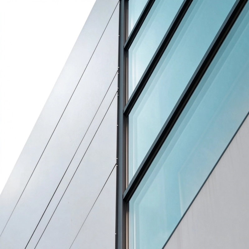
For this reason, designers should establish acceptable joint-width tolerances and coordinate them with panel fabrication, support-frame installation, and site measurement procedures. Where significant deviations occur, the joint should be assessed against the approved design rather than corrected by simply adding more sealant.
Joint depth is equally important, but it is often misunderstood. A deeper sealant bead is not automatically stronger or more durable.
For many conventional elastomeric facade sealants, a properly designed joint uses a controlled width-to-depth relationship and a backing material to establish the required sealant profile. The exact dimensions depend on the sealant manufacturer's instructions, joint width, expected movement, and applicable project standards.
If the sealant is excessively deep, more material may be required to deform as the joint opens and closes. This can increase restraint and alter stress distribution.
If the bead is too shallow, it may lack the geometry or material thickness needed to maintain performance under the intended movement conditions.
It is to create the correct geometry for the specified material.
A suitable backing rod or bond-breaker can help control sealant depth and prevent unwanted adhesion to the back of the joint. In many conventional two-sided adhesion details, the sealant is intended to bond to the two opposing joint faces rather than three surfaces. Unintended three-sided adhesion can restrict deformation and increase stress within the sealant.
However, backing materials and joint details must be compatible with the chosen sealant and the specific facade application. They should be selected according to the manufacturer's guidance and the approved project detail.
The specified joint dimensions must remain achievable throughout panel positioning, substrate preparation, and sealant application.
Even a carefully calculated joint can underperform if the installation sequence does not preserve the intended dimensions.
Aluminum facade systems involve multiple interfaces: panel edges, subframes, brackets, fasteners, perimeter openings, and adjacent building elements. Errors at these interfaces can accumulate. A small positioning deviation at one support may shift a panel edge, while several adjacent deviations can create a joint that varies noticeably from top to bottom.
This matters because sealant performance depends on local conditions. A bead applied to a 15 mm joint may be suitable under the specified design, but the same detail may not be appropriate where the gap narrows substantially or becomes irregular.
Checking panel alignment and actual joint widths before sealant application.
Confirming that joint dimensions remain within the approved tolerances.
Inspecting substrate edges for damage, contamination, coatings, or residues that could affect adhesion.
Verifying backing material placement and sealant depth before the joint is closed off.
Applying sealant within the specified temperature and environmental conditions.
Allowing the sealant to cure according to the manufacturer's instructions before exposing it to conditions that could compromise the installation.
Construction temperature also influences the work. Temperature affects panel dimensions, sealant application behavior, and curing conditions. A joint sealed during a hot afternoon may have a different width from the same joint on a cold morning. If application temperature is ignored, the sealant may begin its service life under a different deformation state than intended.
Surface skin formation must also be distinguished from full curing. A sealant may develop a skin before it has cured through its full depth. Moving, tooling, or exposing the joint prematurely can compromise the finished bead, depending on the product and conditions.
These checks are not merely workmanship preferences. They connect the design assumptions to the actual conditions under which the facade will operate.
Aluminum facade panels may have painted, coated, anodized, or otherwise treated surfaces. Adjacent materials may include glass, stone, concrete, metal framing, or other facade components. Their surface chemistry and condition can affect adhesion differently.
Compatibility should therefore be verified for the actual substrate and sealant combination. Where required, primer selection and adhesion testing should follow the sealant manufacturer's recommendations and project specifications. Testing representative materials is especially important when coatings, finishes, or backing products differ from those used in previous installations.
Failure can occur even when the width and depth are correct. Contaminated surfaces, incompatible coatings, unsuitable primers, or poor preparation may cause the sealant to detach from the substrate.
Conversely, a compatible material may still fail if the joint dimensions force it beyond its intended movement range.
This distinction helps avoid a common mistake in facade maintenance: assuming that every leak can be solved by changing the sealant product. Before replacement, the cause should be traced through joint geometry, installation records, substrate condition, and the surrounding facade details.
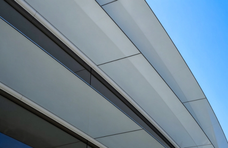
A reliable detail accounts for the range of dimensions that can occur in a completed facade, not just the nominal dimensions shown in drawings.
The most useful shift in thinking is to treat installation tolerance as part of joint design, not as a separate construction issue.
A drawing typically shows a nominal joint width and a specified sealant detail. The installed facade, however, contains a range of actual dimensions. A robust detail must account for that range while preserving the required movement capability and sealant geometry.
This calls for coordination between the facade designer, panel manufacturer, installer, and sealant supplier. The team should confirm the expected movement, allowable dimensional variation, joint-width range, required sealant depth, backing arrangement, substrate preparation, and application conditions before work begins.
Where tolerances cannot be maintained, the correct response is to review the detail and determine whether an approved adjustment is needed. Forcing an unsuitable bead into an irregular opening can hide a dimensional problem without resolving it.
Inspection should also focus on the completed joint profile rather than appearance alone. A smooth surface does not prove that the sealant has the correct depth, adequate adhesion, or the intended bond configuration.
In short, a reliable sealant joint is not created by filling a gap; it is created by controlling the geometry and conditions under which the sealant must perform.
Panel construction, support arrangements, fixing methods, and installation sequencing all influence the joint dimensions available for sealing.
For aluminum composite panels, fire-resistant composite panels, and aluminum honeycomb systems, joint detailing should be coordinated with the panel construction, support arrangement, fixing method, and expected facade movement.
The relevant question is how the complete assembly manages dimensional variation and transfers movement to the joints. Panel fabrication accuracy, subframe positioning, connection details, and installation sequencing all influence the final gap available for sealing.
WILLSTRONG®, established in 1995, develops facade products including aluminum composite panels, fire-resistant composites, and aluminum honeycomb systems. In projects using these panel systems, coordination between panel dimensions, supporting structures, and joint details is important for translating design requirements into consistent site conditions.
Project teams can review the WILLSTRONG® project portfolio to explore facade applications and identify relevant system considerations. Actual joint dimensions, sealant selection, compatibility requirements, and installation tolerances should still be confirmed against project drawings, product technical data, and approved installation procedures.
When evaluating facade suppliers and installation teams, buyers should look beyond panel specifications alone. Useful questions include whether fabrication tolerances are documented, how panel alignment is checked on site, how joint dimensions are verified before sealing, and how deviations are handled. These controls help reduce the risk of a gap between the intended design and the installed facade.
Reliable facade joints depend on coordinated decisions throughout design, fabrication, and installation.
A facade joint may occupy only a small part of the building envelope, but its performance depends on decisions made across design, fabrication, and installation.
Correct width, controlled depth, compatible substrates, and realistic installation tolerances work together. Neglecting any one of them can undermine the others, even when the sealant meets its published specifications.
It begins with a design that accounts for the building as it will actually be built.